Original Link: https://www.anandtech.com/show/586
AMD Thunderbird & Duron Overclocking Revealed
by Anand Lal Shimpi on July 19, 2000 3:54 AM EST- Posted in
- Guides
Last week we published our AMD Thunderbird/Duron Investigation & Overclocking Discussion and basically revealed that the FIC AZ-11, with a few modifications, has the ability to adjust the clock multiplier of Socket-A processors, final shipping “retail” CPUs as well as the engineering samples that we reviewed not too long ago.
The problem we ran into was that, in spite of the fact that we could lower the clock multiplier of our CPUs from their default setting to all lower settings, we could not effectively overclock the CPU by selecting a higher clock multiplier. Selecting a higher clock multiplier would result in the system not even posting. We knew heat was not an issue because running our 1GHz (10.0x) Thunderbird at 1050MHz (10.5x) would not work while we could run the same CPU at the 105MHz FSB setting without changing the clock multiplier (effectively 1050MHz) and it would work just fine.
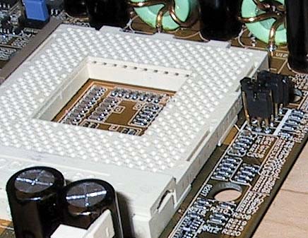
Our home-made OVERRIDE pins on the FIC AZ-11
Because of this we concluded that there was some other factor limiting us from increasing the clock multiplier, most likely the CPU itself. Shortly after publishing the investigation we received a few retail CPUs that we also tried in our modified FIC AZ-11. The results were identical to the experience we had with our “engineering samples” in that using the ‘FID’ jumpers we soldered onto the AZ-11 would only allow us to underclock our CPUs but not increase their clock multiplier above what they were shipped at. Increasing the clock multiplier beyond their shipped state would result in the system not booting, which turned out to be a hint as to exactly what was going on.
If you remember the first ever Overclocking Guide that was published regarding the old Slot-A Athlons by Tom’s Hardware, you’ll remember that in order to change the clock multiplier of the older Athlons you have to manipulate two sets of pins: the four FID pins and the four BP_FID pins. If the two settings didn't match, then the system wouldn't boot.
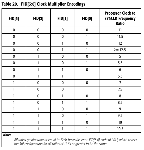
We originally assumed that the four jumpers we soldered onto our AZ-11 corresponded to the four FID settings Tom published in his first Thunderbird Overclocking Guide since adjusting them according to the settings Tom published worked perfectly.
An email from Tom Shaver, the creator of our favorite Slot-A ‘Golden Fingers’ overclocking device the K7OC, proved our hypothesis wrong. Tom Shaver pointed out the possibility that the new Thunderbirds and Durons have the same FID and BP_FID pins that are on the older Slot-A Athlons and that the four jumpers we were setting were only setting one of the two and in order to actually increase the clock multiplier we’d have to find and adjust the second set of pins. But what pins?
We already know the four FID pins from Tom’s first Socket-A Overclocking article, the pins are W1, W3, Y1 and Y3 which can be seen in the picture below:
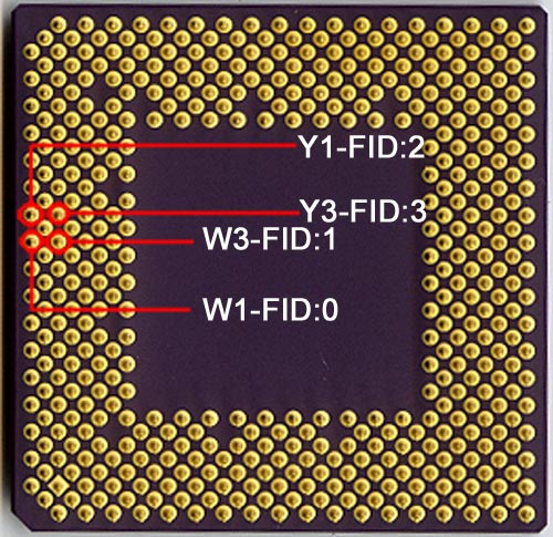
The first thing we noticed when we found the ‘OVERRIDE’ jumpers on our AZ-11 was that these four pins are nowhere near the ‘OVERRIDE’ jumpers, which made very little sense to us at the time since it would require FIC to route the traces (which were visible on the top layer of the PCB) essentially around the socket before making the way to those pins; it would’ve been much easier for FIC to plant the jumpers on the side of the socket closest to the FID pins.
Here’s where Tom Shaver’s suggestion that the FID and BP_FID pins both must be controlled comes into play. If the four ‘OVERRIDE’ jumpers weren’t close to the FID pins of the CPU, maybe they were actually controlling the BP_FID pins on the CPU?
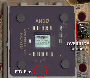
In order for that theory to hold up, two things are required: 1) the BP_FID pins on the CPU would have to be close to the actual ‘OVERRIDE’ jumpers on the AZ-11 board, unlike the FID pins which are a decent distance away from the jumpers and 2) the BP_FID settings would have to be identical to the FID settings (since we thought that we were controlling the FID settings and used the FID settings from AMD to adjust the clock multiplier of our CPUs).
In order to confirm the first condition, we would have to test each and every pin to find out if it actually was a BP_FID; luckily, someone already took care of that for us. One of the best sites in our community (at least in our opinion), Ace’s Hardware, has been known for having an extremely technical message board. A poster on their board, John C. discovered the four undocumented BP_FID pins on the Thunderbird/Duron.
It turns out that pins AN27, AL27, AN25 and AL25 correspond to BP_FID pins 0 – 3 and guess where they are physically located on the CPU in relation to our four ‘OVERRIDE’ jumpers?
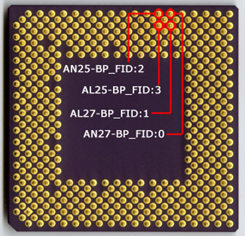
You guessed it, they’re right next to our precious jumpers, so there’s one point in support of the theory that FIC’s ‘OVERRIDE’ jumpers are actually controlling the BP_FID pins and not the FID pins as we originally thought.
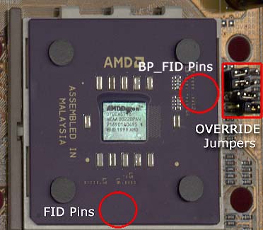
Why couldn’t we figure out that these pins were the BP_FID pins earlier? These four pins are actually listed as NC in the Thunderbird/Duron documentation, NC meaning “not connected.” And normally, if a pin is listed as NC there would be no reason to assume that the docs are lying and it is actually connected. But as John C. managed to find out, the pins are actually connected and are actually the four BP_FID pins we were looking for.
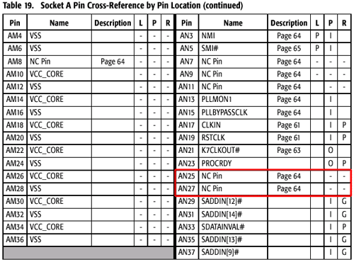
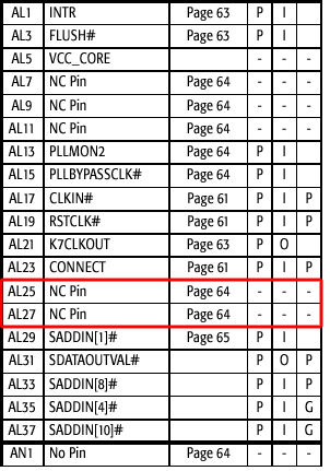
Keep in the back of your head the point that these four pins are listed as NC because that could affect the future overclockability of Thunderbirds/Durons, which we will discuss later, but now back to this theory.
The next thing we had to prove was that the BP_FID settings for the range of acceptable clock multipliers were the same as the FID settings for the multipliers since we were originally manipulating the jumpers based on the assumption that they controlled the FID pins of the CPU.
For this we went to Tom's Hardware's recent publication of the Golden Bridge settings for those of you that wanted to physically modify the “Golden Bridges” on your CPU in order to change the clock multiplier. The chart on Page 4 of his guide documents all of the FID and the BP_FID settings, but if you’ll notice there are only four FID “Golden Bridges” whereas there are twice as many (eight) “Golden Bridges” for the BP_FID settings.
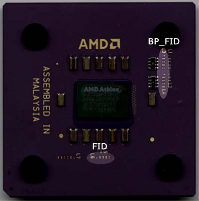
But wait a minute, we just said that the four ‘OVERRIDE’ jumpers on the AZ-11 corresponded to the BP_FID pins, but in Tom’s table there are eight “Golden Bridges” that correspond to the BP_FID pins. So what’s going on?
Instead of simply being connected or disconnected like the FID pins, the BP_FID pins can either be set to Ground (GND) or be pulled up to 2.0V. Because of this characteristic of the BP_FID pins, they require two “Golden Bridges” to set one pin thus explaining the eight “Golden Bridges” that correspond to the four BP_FID pins and this also explains why our ‘OVERRIDE’ jumpers are three pin jumpers that have two settings (1-2 or 2-3) instead of simply two pin jumpers that are either capped or left un-connected.
But let’s get back to proving that the BP_FID settings were the same as the FID settings. If we assume that having the first “Golden Bridge” in a set of two connected and the second left unconnected corresponds to a setting of 1 and vise versa, you’ll notice that the FID and BP_FID settings on Tom's chart are exactly the same for the same clock multiplier.
If you followed all that then you’ll know what the conclusion is: the four ‘OVERRIDE’ jumpers on the FIC AZ-11 that we soldered on our final board control the four BP_FID pins on the Thunderbird/Duron. More specifically, setting the jumpers to 1-2 results in a setting of Ground and setting them to 2-3 results in a setting of 2.0V in the case of the BP_FID pins.
Setting the FID Pins
Now that we know what our ‘OVERRIDE’ pins are actually doing, the question still remains, how do we set the FID pins? This is actually the easy part since we already know what pins on the Thunderbird/Duron correspond to the FID pins; as we mentioned earlier they are: W1, W3, Y1 and Y3.
In order for us to take control of the FID settings, we must first remove the CPU’s ability to tell the North Bridge what clock multiplier it wants. We already have control over the BP_FID pins as we proved with our previous experiment, so if we can gain control over the FID pins we should be good to go.
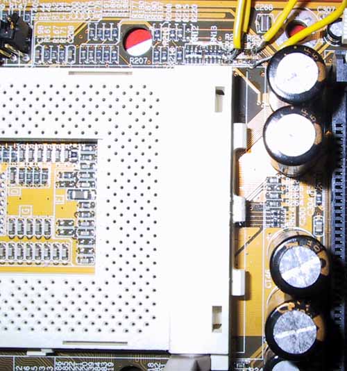
As Hiroji, a Duron owner and hardware enthusiast, documented on his site and as we confirmed, the FIC AZ-11 again turns out to be the perfect candidate for experimentation since the traces going from the four FID pins are present on the bottom layer of the PCB. They could very well be on the top layer or on the middle layers depending on the board design, luckily they are very easily accessible on the AZ-11, the board that we have been experimenting with.
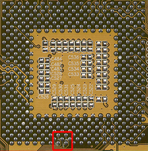
So what do we do with those four traces coming from the FID pins? Well, we have to prevent the CPU from telling the North Bridge what clock multiplier it wants, so we have to physically cut those traces (it sounds bad but it’s much better than removing the pins from the CPU).
Using a lot of patience and an exact-o knife we simply cut the four traces as you can see in picture below:
The final piece of the puzzle is creating our own way of controlling the FID signals that are sent to the North Bridge and this last bit of information is once again provided by Hiroji who discovered that the four resistor positions (they don’t actually hold resistors but are labeled as such) on the AZ-11: R237, R238, R250 & R251 actually control the FID signal sent to the North Bridge.
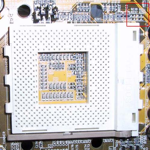
So, after picking up an 8 station dip switch (we only needed to use four stations but our local store was all out of 4 station parts) we went to work soldering our modified AZ-11 yet again. Below you can see the specifics of exactly what positions correspond to what FID pins (the connections were made on the four outermost contact points):
In the end, using a combination of Tom Shaver’s pointers, the technical savvy of Ace’s Hardware readers, Hiroji’s experiments with the AZ-11 and of course Dr. Pabst’s overclocking guides we managed to come up with a method for modifying the FIC AZ-11 that would enable the ability to overclock our CPUs, both engineering samples and currently available parts.
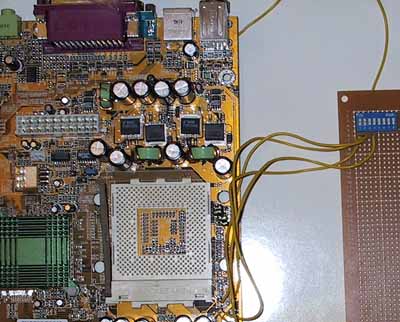
Below you can see a picture of the finished product, it can be cut down in size tremendously by using less wire and a smaller perf board but the point of this was to illustrate that it can be done. Take note that we used the bottom of the PS2 connector as a ground of the dip switches.
Hiroji also provided information on how to adjust the voltage sent to the CPU using another modification to the AZ-11, and if you’re interested you can read about it at his site, however we simply chose to connect the “Golden Bridges” using a conductive pen at L7 on our CPUs to increase the core voltage to improve stability when overclocking.
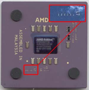
Thunderbird core voltage settings
Overclocking Success
If we were to say that we were successful overclocking our two Durons and our three Thunderbirds we would be lying -- we were more than just successful. Our 700MHz Durons both hit 950MHz without a hitch, and they could both hit 900MHz without even increasing the core voltage past the 1.5v default. Combining this with Tom’s success with his four Durons at 950MHz and Hiroji’s success with his Duron 600 at 900MHz, we can predict that most Durons should be able to hit 900 – 950MHz without much effort at all.
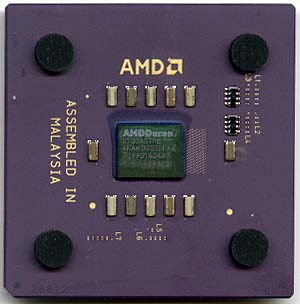
We tried overclocking our Durons to 1GHz and it simply wouldn’t work, even after boosting the core voltage to 1.850v; 950MHz was seemingly the highest we could go, which still isn’t bad for a sub $150 CPU.
Our 1GHz Athlon (Copper) hit 1.1GHz at its default core voltage setting as well, 1150MHz was too high for it to cope with but a 10% overclock isn’t bad at all.
We also tried out an OEM Athlon 700 which was also able to hit 950MHz without increasing its core voltage any over the standard 1.70v it was set to run at. Once again, trying to shoot for 1GHz proved to be futile as the CPU wasn’t stable at that speed.
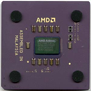
Combined with our experiences with the Duron as well as the Austin made (Aluminum) Thunderbird parts, it seems like there is a reason that all 1GHz Thunderbirds are using Copper interconnects and are thus being made in AMD’s Dresden plant.
Final Words
We’ve proven that the clock multiplier of the Thunderbird/Duron can still be modified, including on currently shipping CPUs as we went out and got our hands on a few currently available CPUs to make sure.
And we’ve already shown how it can be done on one motherboard in particular, the FIC AZ-11, but there shouldn’t be anything stopping ASUS, ABIT, AOpen, Gigabyte, Microstar or any other company from implementing a similar control on their boards as well without forcing us to modify the boards ourselves.
So is there any potential downfall to our recently discovered methodology? Well, the possibility still remains that AMD could simply disconnect the four BP_FID pins from the die, which we would have guessed would be the case since they are listed as ‘NC’ in the currently available documentation on the Thunderbird/Duron.
For whatever reason, the currently available Thunderbird/Duron CPUs have these BP_FID pins connected to the die, and if AMD really wants to prevent unscrupulous vendors from selling overclocked systems they could very easily make sure that the four BP_FID pins aren’t bonded to the die. Whether or not they will is another question and only time will tell if they will pursue that avenue of multiplier locking.
Update - 7/19/2000
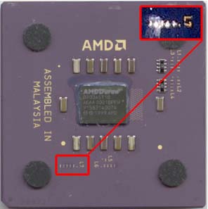
We've received quite a few emails indicating that some of the newer retail Thunderbird and Duron CPUs are completely locked by AMD. The method AMD is using to achieve this is apparently be cutting all of the "Golden Bridges" present at L1, a picture of our CPU with these bridges intact can be seen below:
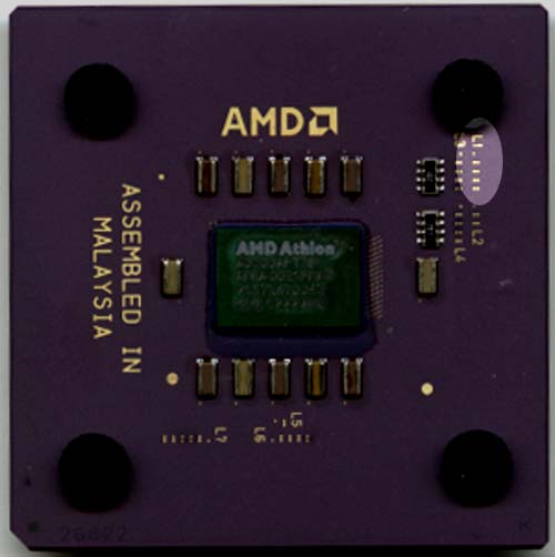
If you happen to receive a CPU that has all of these bridges cut, using a conductive pen or conductive epoxy you can simply rejoin the bridges and your CPU should be able to be unlocked again. There is still no word if AMD will be completely disconnecting the BP_FID pins from the die yet, but for now it seems like we're still good to go.

